

PROBLEM STATEMENT
At Buguruni traffic light system has a lot of limitation at road junction. The system is flexible or in other words cannot be modified on real time. During high Traffic flow at Buguruni junction a Traffic police has to intervene and take control of flow of traffic. When a traffic police take control to replace lights, he/she stands at the center of the junction, hence become prone to accidents and health problem due to inhalation of dust and car smoke from moving vehicles.
PROJECT OBJECTIVES
The main objective of this project is designing of traffic light control system which will enable the traffic police to control the jam while sitting in the control room located nearby the traffic junction.
SPECIFIC OBJECTIVES
The specific objectives adopted to achieve the main objective in this project are to:
i. To identify the circuit requirement
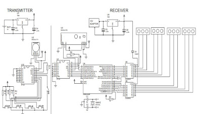
ii. To design a remote control device for controlling traffic lights
iii. To design a remote controlled circuit for Traffic light control
iv. Simulation of the circuit
v. To build the prototype and test the circuit
METHODOLOGY
This chapter explain various steps or procedures that will be taken in order to accomplish the project objectives.
- Literature review
- Data collection
- Data analysis
- Interfacing of the system
- Circuit implementation and test of prototype
- Report writing
LITERATURE REVIEW
Existing system
In Dar es salaam, Tanzania the traffic congestion especially at the intersection is regulated by Traffic signals. The operation of this traffic signal based on the predetermined timing circuit in such that Traffic signals at each intersection can alter their signal sequence based on specific time set up using this timing mechanism.
when it comes to the matter of emergency cases, a traffic officer has to intervene and take control conflict lanes leaving the emergency vehicles pass through without waiting, and respond to their emergencies immediately while smoothing traffic flow.
Data analysis
LED calculations.
Common LED ≈
Vf = 3.3V
If typ = 20mA
For 3 – LEDs = 3 x 20mA
If typ = 60mA x 4 directions = 240mA
Supply Vcc = 5V
R= ?
RT = (Vcc – 3.3) / ( 3x20X10 -3 )
RT = (5V – 3.3V) / (60 x 10 -3) = 28.33Ω
From the standard (ER) value, RT = 33Ω
Relay driver ULN2003A
Vcc = 5V / Trigger / 3.3V
Switch up to 50V
Max current control I= 500A
Sinking current = 1.35mA
Decoder:
Vcc = ( 2.4 – 12V)
Current Sinking = ±1uA
Receiver:
Vcc = ( 3V – 12V)
Current Sinking = 3.5mA
ATmega328p
Supply voltage operate =1.8V to 5V
Minimum output current =0.5mA
Maximum output voltage =20mA
Reset Pin for Control Unit
From V=IR
To find the value of resistor
𝑅=𝑉/𝐼
𝑅=5𝑉/0.5𝑚𝐴
𝑅=10𝐾Ω
Power supply
A 230V, 50Hz ac supply is stepped down by a transformer to a secondary voltage of about 18V. The stepped down voltage is then rectified by using a bridge rectifier
Consider the following;
Peak primary voltage (Vp) = 230 × √2 = 325.23V
Peak secondary voltage (Vp) = 18×1.414=25.506V
Peak voltage from diode (Vp) = 25.506 – 1.4 =24.1V.
Therefore Vdc = Vp / (1+ 1/2𝐹𝐶𝑅 )
= 24.1V/ (1+1/(2×50×10×1000µ))
Therefore, Vdc= 12.05V
Supply voltage frequency = 50Hz
Selection of capacitor for filtering
The relationship between the ripple voltage (rms) and the filtering capacitor:-
C=𝐼𝑑𝑐/(4√3×𝐹×𝑉𝑟𝑚𝑠)
Where, Idc = DC output current from the filter (mA)
Vr (rms) = Rms value of ripple voltage (V)
f = Supply frequency (Hz)
C = Filter capacitor (µF
The current from a filter circuit is a dc current and is about few mA to 1A.Idc of 1A = 1000mA, ripple voltage Vr(rms) of 2.887V, supply frequency of 50Hz, then the value of capacitor filter will be
C=(1000×0.001)/(4√3×2.887×50)=999.4µF
This obtained filter capacitor of 1000μF is selected based on the available standards in the market.
A filter capacitor of 1000µF is selected and used in a circuit because large capacitors eliminate large amount of ripples


0 Comments